


Electrical Automation Control: Industrial Control Terms, Instrumentation and Measurement Terms
Electrical Automation Control: Industrial Control Terms, Instrumentation and Measurement Terms
Industrial Control
Closed - Loop Control
A fundamental concept in control theory, closed - loop control differs from open - loop control by feeding the controlled output back to the input end to influence control. This feedback mechanism allows the output to return to the input via a "side chain," enabling the input to exert control over the output. The primary purpose of closed - loop control is to achieve feedback - based regulation.
I/O Points
A frequently used term in control systems, I/O points refer to Input/Output points. Inputs are measurement parameters from instruments entering the control system, while outputs are control parameters sent from the system to actuators. The scale of a control system is often defined by the maximum number of I/O points it can accommodate.
Analog and Switching Quantities
In control systems, parameters can be analog or switching quantities. Analog quantities are continuously varying values within a specific range, such as temperature or pressure. Switching quantities, however, have only two states, like the on/off states of a switch or relay.
Control Loop
For analog control, a controller adjusts an output based on an input using specific rules and algorithms, forming a control loop. Control loops can be open - or closed - loop. Closed - loop control, or feedback control, is the most common type, where the output is fed back to the input for comparison with the set value.
Two - Position Control
The simplest form of feedback control, also known as switch control. It triggers a switching signal when the measured value reaches a maximum or minimum. Although the measured value may be analog, the control output is digital. This method is commonly used in industrial thermoregulators and level switches.
Proportional Control
The controller's output is proportional to the deviation between the measured value and the set value or reference point. Proportional control provides smoother regulation than two - position control and eliminates the oscillation issues associated with two - position control.
Integral Control
In integral control, the change in the controlled variable is related to the time it takes for the control system's output to become effective. The actuator's output gradually reaches the set value. This control method is commonly used in temperature control systems.
Derivative Control
Derivative control is typically used in combination with proportional and integral control. It allows the control system to respond to deviations more quickly, preventing sluggish system responses. Together with proportional and integral control, it helps the controlled variable reach a stable state more rapidly without oscillation.
PID Control
Depending on the specific requirements of the control system, control methods can be P (Proportional), PI (Proportional - Integral), PD (Proportional - Derivative), or PID (Proportional - Integral - Derivative) control. PID control is the most common control mode in control systems.
Delay Control
* Commonly used in switching control applications, delay control introduces a time delay between a switch state change and the controller's output action. For example, in production lines, proximity switches often require a delay of several seconds before the next roller begins operation after a workpiece is positioned.
Interlock Control
* Frequently used in switching control scenarios, interlock control establishes relationships between switches. For instance, switch C can only be activated when switches A and B are both open, or switch C must open when switch A opens. Interlock control is common in safety - critical applications, such as the vent valve in a reactor, which must open immediately when the pressure reaches a certain level.
Electric Control
* Refers to control systems where the output is achieved through electrical quantities or electronic signals, targeting electrically driven components like relays, solenoid valves, and servo drivers. Most automatic control systems incorporate electric control elements.
Hydraulic Control
* Hydraulic control systems are used in machine and equipment operations, particularly in continuous speed control applications. Hydraulic control is often combined with electric servo control to form highly efficient and precise electro - hydraulic actuators.
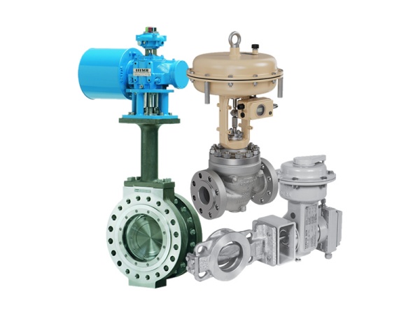
Pneumatic Control
* Pneumatic control systems are employed in various scenarios. They utilize compressed air as the power source for signal transmission or actuation. Compressed air is widely used in factories due to its availability, cleanliness, safety, and simple control functionality, making pneumatic tools common in many production lines.
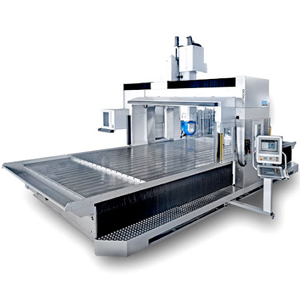
Interpolation
* Interpolation is the process by which a machine tool CNC system determines the tool path using a specific method. It involves calculating intermediate points between known data points on a curve, also known as "data point densification." The CNC system generates the required contour trajectory by densifying the data between the start and end points of a program segment.
Position, Velocity, and Current Loops
* The concept of loops involves using feedback to enhance the stability and performance of application systems.
* Current loop control aims to regulate voltage by using current signal transmission to compensate for losses, voltage drops, and noise during voltage transmission.
* The relationship between speed and position is based on the formula: distance = speed × time. The continuous variation of speed over a time interval results in the integral of speed over that interval, which corresponds to the distance traveled (position).
* The relationship between speed and current is defined by: speed = acceleration × time. Acceleration depends on the applied current, and the integral of acceleration over a time interval yields the instantaneous speed.
* In torque control mode, the servo motor rotates at a set torque by maintaining a constant output from the current loop. If the external load torque equals or exceeds the motor's set output torque, the motor's output torque remains constant, and the motor follows the load movement. Conversely, if the external load torque is less than the motor's set output torque, the motor continues to accelerate until it reaches the maximum allowed speed of the motor or drive, at which point an alarm is triggered and the motor stops.
* In velocity mode, the motor speed is set, and the speed feedback from the motor's encoder forms a closed - loop control system. The purpose is to ensure that the actual speed of the servo motor matches the set speed.
* The control output of the velocity loop serves as the torque - mode current - loop torque setpoint. In position control mode, the position setpoint provided by the host computer and the position feedback signal from the motor's encoder or the direct position measurement feedback from the equipment are compared to form a position loop. This ensures that the servo motor moves to the set position. The output of the position loop is fed into the velocity loop as the velocity - loop setpoint. Thus, torque - control mode utilizes the current - control loop as the most fundamental layer. The velocity - control loop is built upon the current - control loop, and the position - control loop is built upon both the velocity - and current - control loops.
Instrumentation and Measurement Terms
Range
A continuous interval of a quantity defined by upper and lower limits.
Measuring Range
The range of measured values for which the instrument can achieve the specified accuracy.
Measuring Range Lower Limit: The minimum measured value for which the instrument can achieve the specified accuracy.
Measuring Range Upper Limit: The maximum measured value for which the instrument can achieve the specified accuracy.
Span
The algebraic difference between the upper and lower limits of a range. For example, if the range is from -20°C to 100°C, the span is 120°C.
Performance Characteristic
Parameters that define the function and capability of an instrument and their quantitative expressions.
Reference Performance Characteristic: The performance characteristic achieved under reference operating conditions.
Linear Scale
A scale where the spacing between scale divisions and the corresponding measured values have a constant proportional relationship.
Nonlinear Scale
A scale where the spacing between scale divisions and the corresponding measured values have a non - constant proportional relationship.
Suppressed - Zero Scale
A scale where the scale range does not include the scale value corresponding to the zero value of the measured quantity.
Expanded Scale
A scale where a disproportionate portion of the scale length is occupied by an expanded section of the scale.
Scale
A set of ordered scale marks and associated numbers that form part of an indicating device.
Scale Range
* The range defined by the start and end values of the scale.
Scale Mark
* A mark on the indicating device corresponding to one or more specific measured values.
Zero Scale Mark
* The scale mark or line on the scale corresponding to the zero value of the measured quantity.
Scale Division
* The portion of the scale between any two adjacent scale marks.
Scale Division Value
* The difference between the measured values corresponding to two adjacent scale marks.
Scale Division Spacing
* The distance between the center lines of any two adjacent scale marks along the scale length.
Scale Length
* The length of the line segment, either real or imaginary, passing through the midpoints of all the shortest scale marks between the start and end scale marks.
Scale Start Value
* The measured value corresponding to the start scale mark.
Scale End Value
* The measured value corresponding to the end scale mark.
Scale Numbering
* The set of numbers on the scale corresponding to the measured values defined by the scale marks or indicating the order of the scale marks.
Zero of a Measuring Instrument
* The direct indication of a measuring instrument when all auxiliary energy required for its operation is applied and the measured value is zero.
* In cases where the measuring instrument uses auxiliary power, this term is usually referred to as the "electric zero."
* When the instrument is not in operation due to the absence of any auxiliary energy, the term "mechanical zero" is often used.
Instrument Constant
* A coefficient by which the direct indication of a measuring instrument must be multiplied to obtain the measured value.
Characteristic Curve
* A curve showing the functional relationship between the steady - state output value of an instrument and one input quantity, with all other input quantities maintained at specified constant values.
Specified Characteristic Curve
* The curve showing the functional relationship between the steady - state output value of an instrument and one input quantity under specified conditions.
Adjustment
* Operations carried out to ensure the instrument is in normal working condition and to eliminate deviations for proper use.
* **User Adjustment**: Adjustments allowed to be performed by the user.
Calibration
* The operation of establishing, under specified conditions, the relationship between the values indicated by a measuring instrument or system and the corresponding known values of the measured quantity.
Calibration Curve
* A curve showing the relationship between the measured quantity and the actual measured value of the instrument under specified conditions.
Calibration Cycle
* The combination of the upward calibration curve and the downward calibration curve between the calibration range limits of an instrument.
Calibration Table
* A tabular representation of the calibration curve.
Traceability
* The property of a measurement result that can be related to appropriate standards (usually international or national standards) through an unbroken chain of comparisons.
Sensitivity
* The quotient of the change in the instrument's output and the corresponding change in the input quantity.
Accuracy
* The degree of consistency between the instrument's indication and the true value of the measured quantity.
Accuracy Class
* The classification of instruments according to their accuracy.
Limits of Error
* The maximum permissible error of an instrument as specified by standards or technical specifications.
Basic Error
* The error of an instrument under reference conditions.
Conformity
* The degree of consistency between the standard curve and the specified characteristic curve (such as a straight line, logarithmic curve, parabolic curve, etc.).